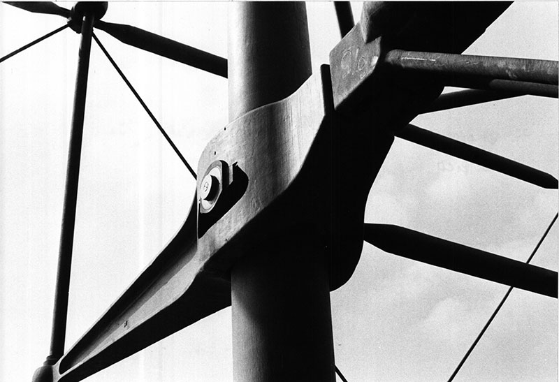
Beside a massive round column projects a long, tapering steel arm. It swells near the column and narrows as it extends down to the left. A conspicuous circular connection sits beside the column; a slender vertical rod meets the far end of the arm. Other diagonal lines run behind it, but its outline does not disappear among them. The black-and-white photograph makes it look like an object with a head, a waist and an extremity. View the official close-up of the connection
This component has a specific name: gerberette, referred to here as a cast-steel bracket arm. It connects the large floor beam, column and outer tension rod. The end that looks slender in the photograph is not hanging freely in space. The vertical rod belongs to the system that makes it work.
We often recognize the Centre Pompidou in Paris by its coloured pipes and diagonal escalator. Beginning with this less conspicuous component brings us closer to a more fundamental choice: to keep fixed load-bearing walls and rows of columns from dividing the interior, the designers concentrated much of the structure, circulation and building services at the perimeter. The rooms’ freedom to change their arrangements depends precisely on a framework established in advance.
The Centre Pompidou opened in 1977. Its main building was designed by Renzo Piano, Richard Rogers and their team, with engineers including Arup’s Peter Rice contributing to the structure and services. It brought a museum of modern art, a public library and many kinds of cultural activity into one large building. What deserves close attention here is not the outline of a machine, but how a building makes room for uses that have yet to be determined. The architects’ project information
1 Begin with How the Long Arm Connects
Place the close-up beside the photograph of the external frame, and the isolated steel arm begins to appear in groups. At every level, similar components project beside the round columns. Slender vertical rods continue upward and downward farther out. Diagonal braces cross nearby, while matching columns and brackets recede in rows.
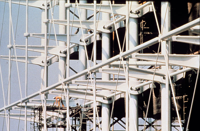
These lines are not all the same kind of thing.
The columns are thick vertical members. The tension rods are thinner, forming another vertical line at the outer edge. The projecting cast-steel arms connect the two. One end meets the large beam inside the building; the other is restrained by the outer tension rod. The beams deliver floor loads to their ends, and bracket arms, columns and tension rods together transmit them toward the foundations. Diagonal bracing helps the whole set of frames resist lateral deformation. Once these distinctions are visible, the dense white mesh becomes a set of components with separate tasks. Rogers’s practice: structural description
The bracket arm’s curved surface particularly rewards a pause. Thick beside the column, it gradually contracts toward its end, with circular edges visible at the connection. Beside the straight members behind it, it seems to slow down around the joint, allowing us to see how two components meet. Its rounded form also has a manufacturing history: this is cast steel, not a shell assembled from ordinary steel plates. In the official factory photograph, enormous uninstalled brackets lie side by side. Their edges, holes and rough surfaces are exposed; workers standing among them make their scale clear.
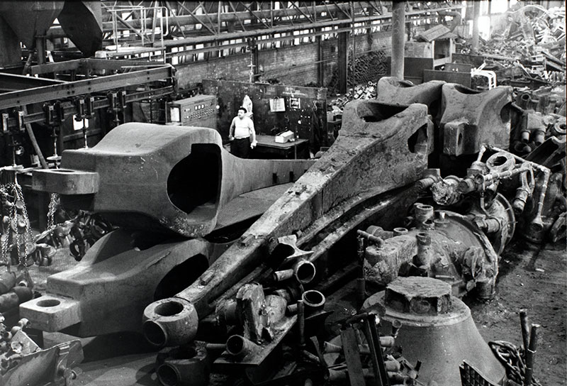
One bracket cannot carry the whole building, however. The visible “joint” has strength because beams, columns, tension rods and braces each take their places around it. If we admire only this component’s sculptural quality, the interior space it helps release disappears from view again.
2 Where the Glass Wall Steps Back
The detail section published by Piano’s practice shows a further interval between the framework and the interior.
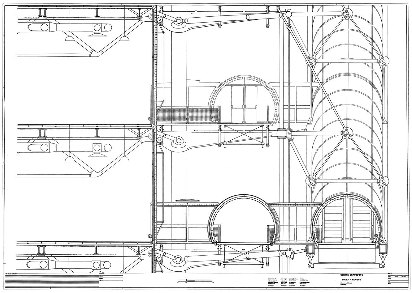
The floor levels are on the left. The diagonal web members of the large beams occupy a definite depth, with lights and services between or below them. At the glass boundary, the floor does not neatly cut off every component. The bracket arms continue to the right, followed in sequence by the round columns, outer tension rods and circulation space. Farthest right is the tubular enclosure around the escalator; between them, the drawing also shows the arched covering of a horizontal walkway.
The external wall is therefore more than “a lot of things attached to glass.” The glass sits behind; structure and circulation occupy a depth in front. The external frame supports the floors while also leaving positions for people to move along their edges. The building boundary divides into separate tasks: shelter from weather, support and passage each have their own line.
Now look at the overall section. Broad horizontal levels spread between the supports at either end of the main building. The circulation zone on the right forms a continuous outer edge, while vertical pipes on the left reach the equipment at the top. Below are underground rooms and parking extending under the piazza. The piazza’s “emptiness” is not simply a whole tract of unbuilt ground.
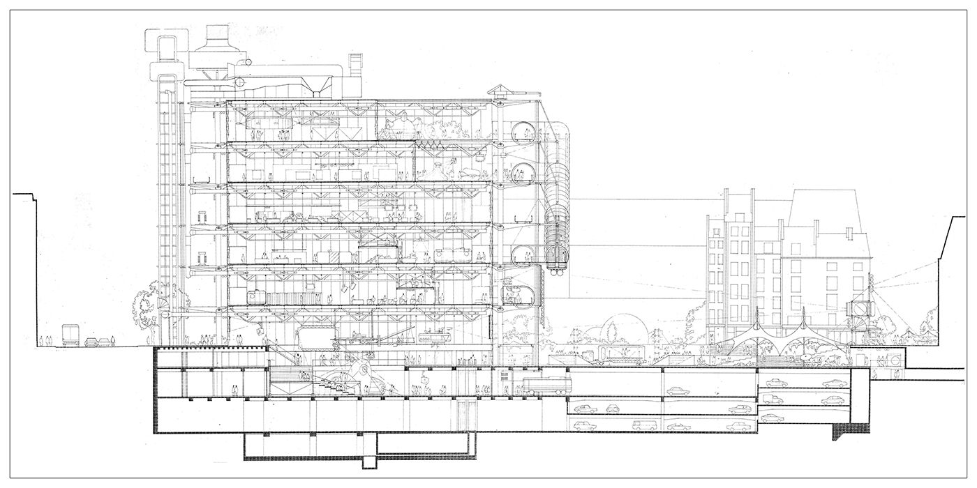
The two design drawings are most useful for breaking the great volume into sections we can follow. They also correct an overly convenient metaphor: the Centre Pompidou has not turned its entire interior inside out. Long-span beams still cross the interior, while ventilation and lighting must ultimately reach the occupants. What moved to the perimeter were components that could be grouped there to occupy less of the main floor area. An open interior does not mean technology has vanished. It means technology occupies space differently.
3 How the Adaptable Floors Have Been Used
Begin with the public library photograph. Rows of tabletops extend into the distance, with small lamps repeating along their edges. Bookshelves gather on the right, a continuous window surface runs along the left. Blue ventilation ducts branch horizontally overhead, beside the diagonal members of dark trusses. No substantial wall nearby divides the reading area into little rooms.
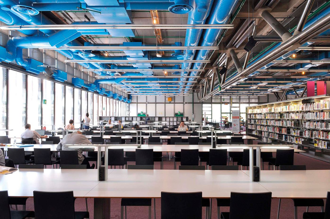
This is not an empty hall. Tables, chairs, shelving and lights have already divided it into particular places for sitting, consulting books and passing through. The scale of the large space becomes smaller at a table. People need not confront the width of the whole floor at every moment. An adaptable floor’s value is not confined to accommodating larger events; it also lies in making room for many quieter, less conspicuous arrangements.
Another photograph, of a gallery, shows a different division. Sculptures and low plinths scatter over a timber floor. A white exhibition wall defines another area on the left, while benches line the glass on the right. The city view continues beyond the people by the windows; ducts, lighting tracks and beams remain overhead. One can stop before a work or step back to see its relationship to neighbouring works and the view through the windows.
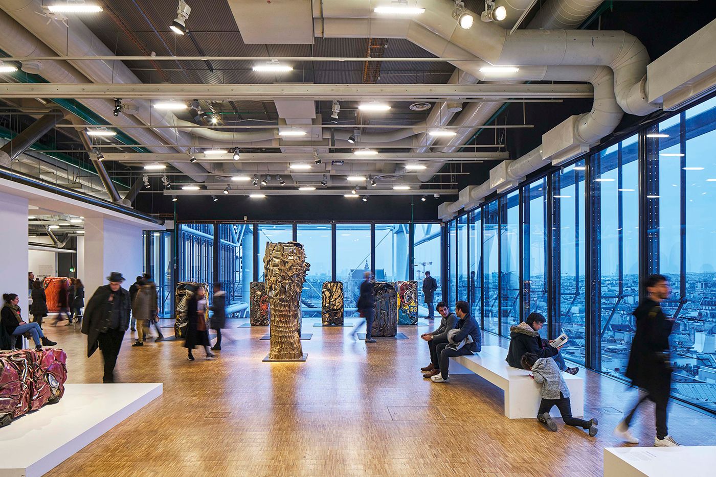
The photographs do not mean that every arrangement can simply be moved anywhere. Shelf loads, lighting levels for artworks and routes for people still require planning. They show something more concrete: not every boundary of use inside must coincide with a load-bearing boundary. Rows of tables and turns of exhibition walls can be decided separately within the larger structural spans.
This freedom has undergone real revision. The museum records that its early arrangement used movable partitions and relatively free routes. Beginning in 1985, alterations led by Gae Aulenti introduced taller exhibition walls and adjusted lighting, creating more clearly defined display units for the growing collection. The interiors seen today include later users’ reconsideration of the original open layout. Flexibility does not mean remaining empty forever. It allows more specific needs to enter. The institution on changes in spaces and uses
4 What Each of the Two Façades Shows
Return from the interior to the frontal photograph of the services façade. The dense vertical blue pipes are most striking. Green pipe bundles gather in several places, red circulation towers pass through the levels, and yellow components add horizontal accents to the background. White diagonal braces maintain their own grid in front of and behind these colours.
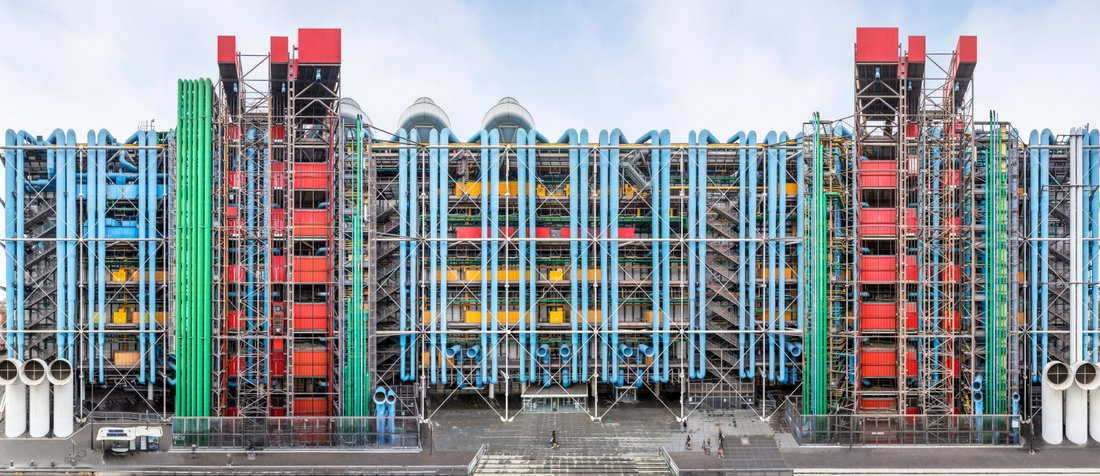
The institution’s colour code assigns blue to air systems, green to water, yellow to electricity and red to the movement of people. Colour helps distinguish categories but does not automatically explain the operation of every line. The eye can begin by following a blue pipe to its upper bend, then see how it turns at a particular floor. Only then does the repetition of colour reveal more than decoration: vertical conveyance and distribution by floor acquire direction on the façade. The institution’s architectural introduction
The side facing the piazza instead brings human movement to the front. In Manuel Braun’s 2016 photograph, the transparent escalator tube crosses layers of fine components: it rises for a stretch, becomes a landing, then rises again. Its broken line cuts across the horizontal and vertical floor grid, yet meets the storey levels again at each landing.
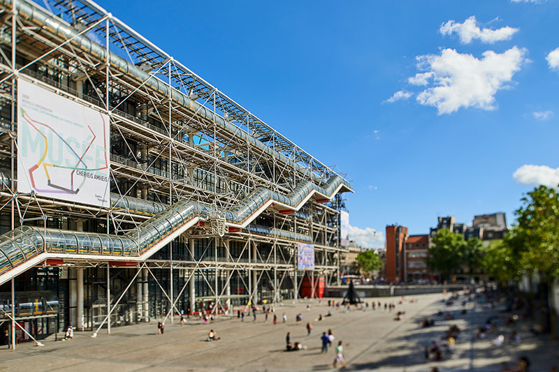
The distance left by the piazza makes the whole broken line visible. Paving in the foreground is broad and open, with people scattered across it; the building retreats into one large backdrop. From the piazza, the escalator makes ascent part of the external outline. From the escalator looking out, the city gradually unfolds with height. External circulation does more here than save floor area inside. It becomes an actual route for viewing the building and Paris.
The transparency in these images still involves doors, glass and rules of access, however. The completely open ground floor originally envisaged was not realized as planned. A piazza next to a hall and unconditional access for everyone at all times are different matters. The architectural invitation takes shape in slopes, entrances and escalator positions. Its continuing fulfilment also depends on use and management.
5 Change Also Requires Maintenance
In this building often called a “machine,” pipes, joints and skin are conspicuous. Their visibility is a visual effect, but also means that they remain participants in the building’s history of use.
The published 2030 renewal programme includes replacing façades and services networks, addressing structural corrosion, and improving energy performance and access. Technical work judges component by component what can remain, what should be remade in its existing form and what needs alteration for use. Proposed changes cannot yet be treated as realized experiences. The programme nonetheless gives “adaptable” real weight: replacement entails construction, money, closure and renewed coordination. It is not as effortless as removing a toy building block. The official renewal programme
Return to the library photograph. Let the eye move from a desk lamp to a blue duct overhead, then to the adjacent truss. Their scales and working cycles differ: the lamp lights one table now, the duct serves an area, and the deep, long truss spans the whole floor. Users rearranging tables and chairs beneath them do not have to reinvent the framework above.
The Centre Pompidou’s most distinctive promise takes concrete form in this relationship between above and below. It carefully establishes spans, supports and service routes first, then lets exhibition walls, shelves and people occupy the space. The projecting cast-steel arm therefore belongs to more than an unusual silhouette on the Paris skyline. It also belongs to the specific conditions that allow a table inside to be placed here without accommodating a row of load-bearing columns.
Optional Further Reading | What Must a Beautiful Joint Still Undergo?
Han Qin’s “Even a Beautiful Theory Has to Wait for the World” discusses the beauty of physics: however convincing relationships on paper may be, they must face tests from reality. At the Centre Pompidou, we can take this thought back to the moment before the bracket arm entered the building.
Open the 1974 lifting photograph. A bracket arm hangs alone from lifting slings, its large hole not yet fitted around the round column. Its slender outer end and swelling middle are clear, but the familiar structural relationship of the complete building does not yet exist. Between a casting in a factory and a dependable joint lie the tasks of material preparation, manufacture and assembly.
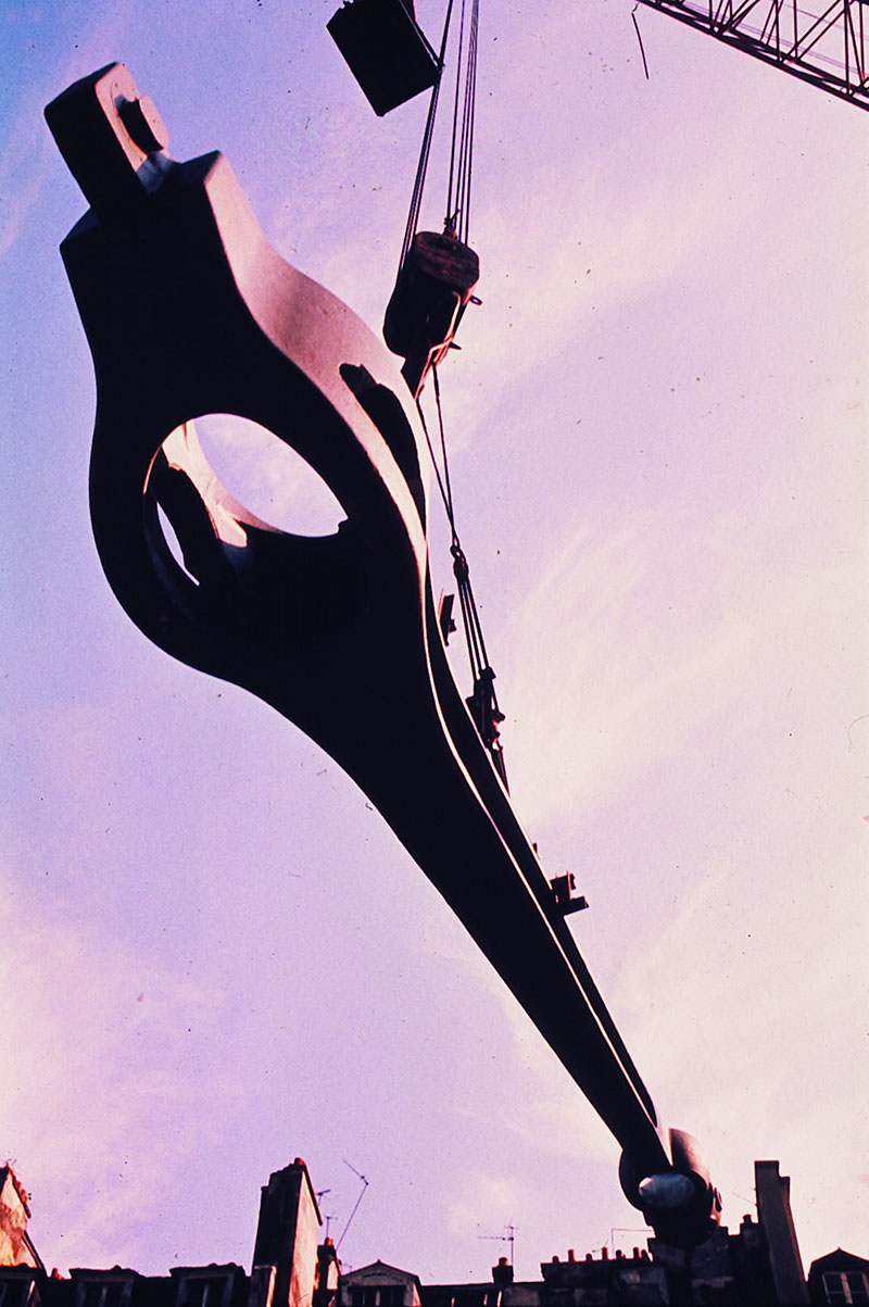
The institution’s 1974 activity report, printed page 21 (PDF page 17) records a process that was far from smooth. Special components and connections required testing and repeated refinement. Large cast-steel pieces called for laboratory research and changes to manufacturing processes. Defects difficult to remedy after installation had to be eliminated through manufacturing inspections. Erection of the steel structure, originally due to begin in June, was postponed until October. The report does not publish measurements for every test, and we should not supply a legendary failure story in their place.
What it adds is a pause that can be checked. Looking at the bracket close-up, we can slide too quickly from the rounded joint, clearly defined members and handsome taper to “of course it can work like that.” The lifting photograph and report restore what that leap omits: form first proposes a possibility, but the manufactured material and connections must actually meet the relevant demands. Visual harmony cannot exempt them from testing.
Looking again at the installed circular connection, we need not admire it less. What deserves attention is precisely that the promise has become more specific: this arm must both receive the large beam and form practicable connections with column and tension rod. We now know that the clear design outline passed through time in factories, tests and refinements. What is borrowed here is the perspective emphasized by SAE (Self-as-an-End)’s beauty of physics: letting an idea receive reality’s answer. It does not mean calling a building a new law of physics.
Images and Sources
This essay closely reads official photographs, construction archives and drawings published by the architects’ practice. It is not a site-visit account. Construction photographs identify components; design sections explain spatial and structural positions. Not every configuration shown in a drawing can be treated as an unchanged later condition. Individual interior photographs are not all dated. They serve here as examples of use before the renewal, not as claimed records of the 1977 original or the building’s access status in 2026.
- Centre Pompidou: the metal exoskeleton: source of the bracket close-up, factory photographs and construction archive images.
- Centre Pompidou: structure and modules: component names, assembly and the photograph of the coloured façade.
- Piano’s practice: project page: source of the two sections, reading-room and gallery photographs; includes information on original construction and later alterations.
- Arup’s 1973 engineering journal issue, printed page 9: description of steel structure and services during construction. Used here to check columns in compression, outer tension members, hinged connections and beams still spanning the interior. Fire-protection proposals then undecided are not used to describe the building today.
- The institution’s feature on the piazza: the 2016 piazza photograph and historical context for the proposed entrance arrangements.